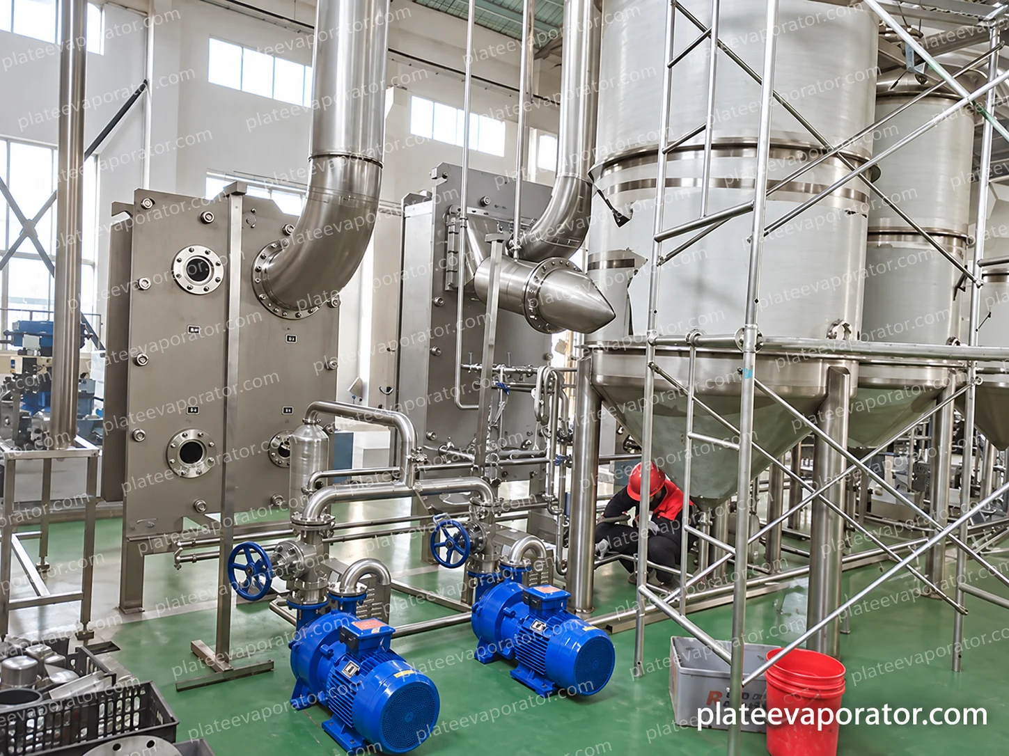
Connect the feed and concentrate on their own conditions
The feed connection receives a liquid with a defined composition, preparation, temperature and flow range. A balance vessel can smooth specified short variations and provide an operating level for the feed circuit. It does not correct a continuous mismatch between upstream supply and evaporation capacity.
Concentrate discharge operates at a different composition and may have a different viscosity and temperature from the feed. Its pump, pipe route and receiving conditions must suit that material. Downstream availability and vessel levels influence how the evaporator responds to a production interruption.
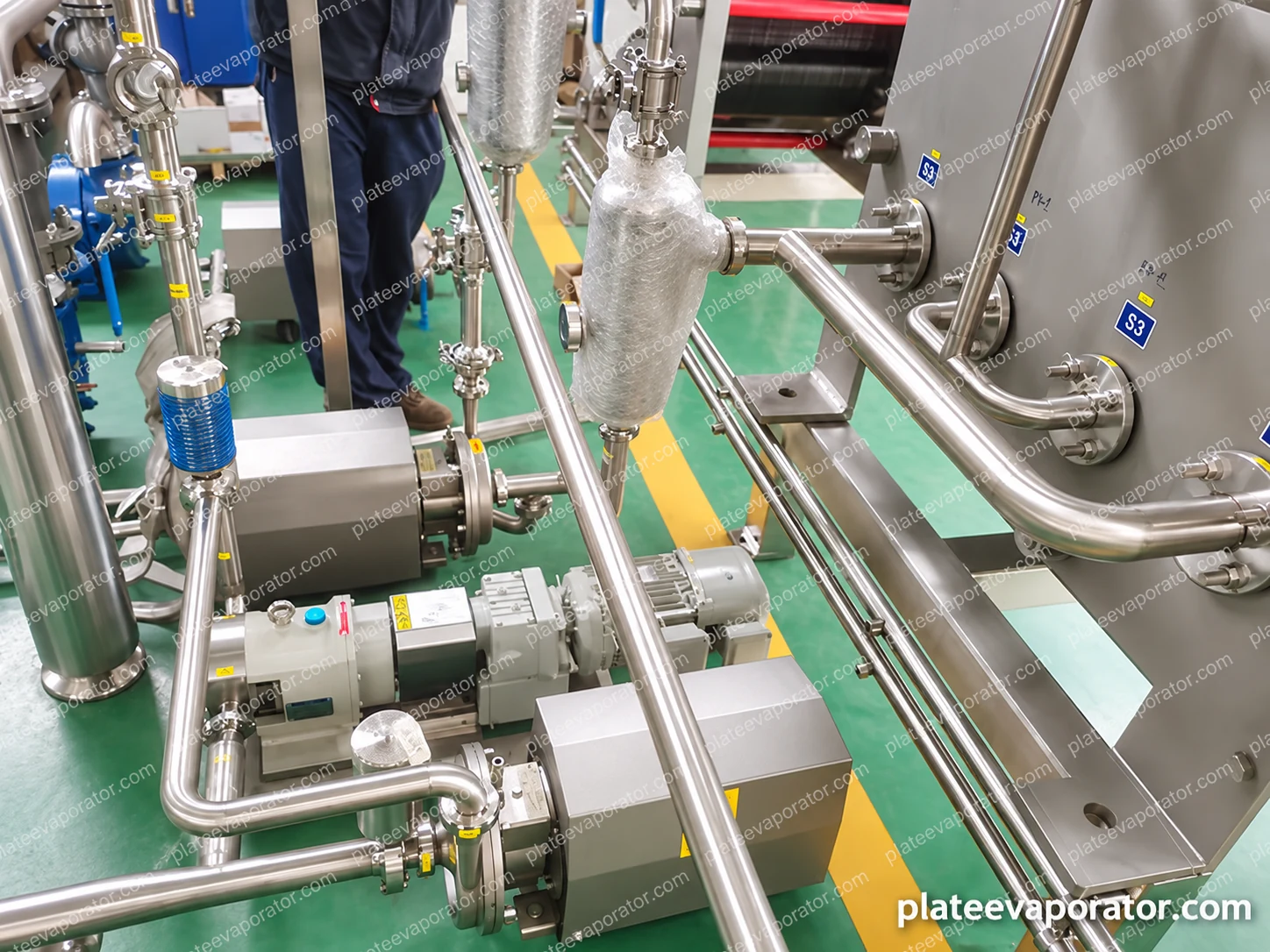
Make each service boundary explicit
The package specification distinguishes equipment mounted with the evaporator from site utility generation and distribution. Normal production, start-up and cleaning can create different service demands.
| Connection | What the system requires | What the site arrangement must address |
|---|---|---|
| Heating supply | The selected medium and operating condition | Available duty, control, isolation and return |
| Cooling | The condenser or other selected cooling duty | Inlet condition, flow, return and seasonal variation |
| Vacuum and vents | Specified pressure and non-condensable-gas handling | Equipment package and its service connections |
| Condensate | Collection from the defined heating or vapour circuit | Destination, quality requirements and separation from product |
| Electrical and controls | Drives, instruments and selected actuators | Supply, interfaces and operating permissions |
| Cleaning and drains | Supply and return for the intended product-contact routes | Compatibility, collection and drainage capacity |
Leave room for plate opening and service work
The plate frames need their specified opening and removal clearances. Vessel access, pumps, valves and instruments also need to remain reachable after surrounding pipes and platforms are installed. Installation planning includes the route by which the supplied modules enter the building.
Product and service lines should drain or retain liquid only as required by the selected design. The layout identifies low points, cleaning returns and the destination of removed liquids. Temporary assembly access shown in a workshop image is not a substitute for permanent plant access.
Use symptoms to locate the affected circuit
Use the installed procedures for investigation and isolation. These checks locate the relevant equipment; they are not directions to bypass an interlock, open a pressurised assembly or change a product process outside its agreed operating window.
| Observation | Relevant checks | Record alongside the checks |
|---|---|---|
| Concentration or water removal drifts | Feed composition and flow, heating condition, pressure and discharge | Matched feed and concentrate samples with operating readings |
| Vacuum condition changes | Cooling performance, condensate routing, air entry and vacuum equipment state | Pressure, cooling conditions and time of the change |
| Pump delivery becomes intermittent | Supply level, inlet condition, air entry and receiving pressure | Liquid temperature, level and flow behaviour |
| Liquid appears in an unintended vapour or condensate stream | Separation condition, level, foaming and the selected internal arrangement | Feed condition, operating event and appropriate samples |
| Duty declines during a run | Feed changes, heating and cooling conditions, flow and potential deposits | Time trend against comparable operating conditions |
| Cleaning return differs from expectation | Valve route, supply, return path and instrument condition | Actual circuit and cleaning-stage readings |
Give each operating state a defined response
The control sequence coordinates feed, heat, vacuum, liquid levels and concentrate discharge. Production, waiting, controlled stopping and cleaning are different states. The selected permissions prevent one section continuing to operate when its required upstream or downstream condition is unavailable.
Instruments and records are selected for those functions and the acceptance requirements. The actual configuration determines alarms, interlocks, operating limits and the permitted restart sequence. A cabinet photograph shows physical controls equipment, not the validation of a particular programme.