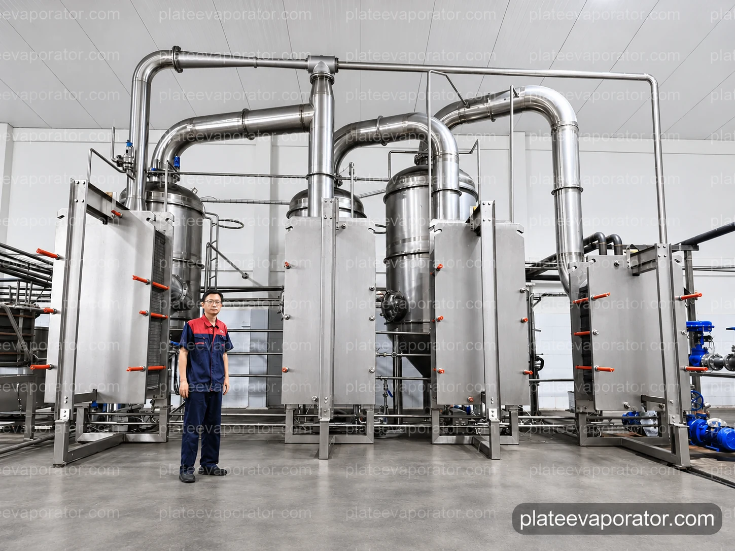
Follow the liquid through a connected system
Feed enters through the receiving and preheating arrangement before evaporation under reduced pressure. The plate section supplies heat, the connected vessel separates vapor from liquid, and the transfer circuit moves the concentrate onward. Vapor has its own route through heat recovery or condensation.
The balance vessel, preheater, evaporating sections, separators, liquid pumps, condenser and vacuum equipment form the process package. Its pipework and controls connect these functions so that feeding, boiling and discharge remain coordinated. A plate heat exchanger by itself does not perform all of these duties.
| Part of the package | Process connection |
|---|---|
| Receiving and preheating | Accept the prepared liquid and bring it toward its selected evaporation condition |
| Plate sections and separators | Add heat, generate vapor and retain the concentrated liquid on its product route |
| Pumps and connecting pipework | Transfer feed, concentrate and condensate through their separate circuits |
| Condenser and vacuum circuit | Handle terminal vapor and gases while supporting the chosen boiling condition |
| Instrumentation and controls | Coordinate operating measurements, alarms and equipment states |
| Cleaning connections | Connect the product route to the selected CIP supply and return |
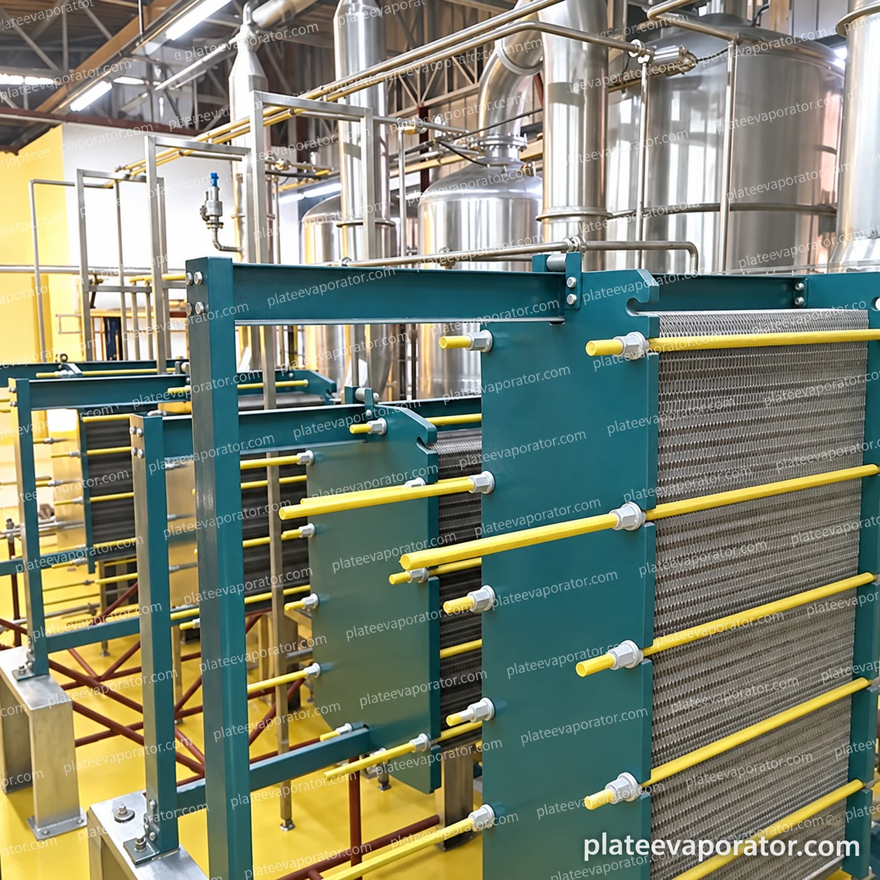
Clamped plate packs with a serviceable frame
The plate pack fits between frame plates held by long tie bolts. The close view shows the stack edges, support bar and clamping arrangement, while the complete-system views show the large connecting pipes and adjacent separation vessels. These parts establish a compact heat-transfer assembly within the wider evaporation circuit.
Product and heating-medium passages transfer heat across the plates. The selected channel arrangement, connections and seals determine the actual liquid path and operating limits. Plate construction can support different process arrangements; the frame shape alone does not define falling-film, rising-film or circulating operation.
Service space belongs alongside the clamping frame. Leave clearance for the specified opening procedure, plate handling and connection removal, then follow the assembly instructions for plate sequence and closing dimension. Seal selection must account for both product exposure and cleaning conditions.
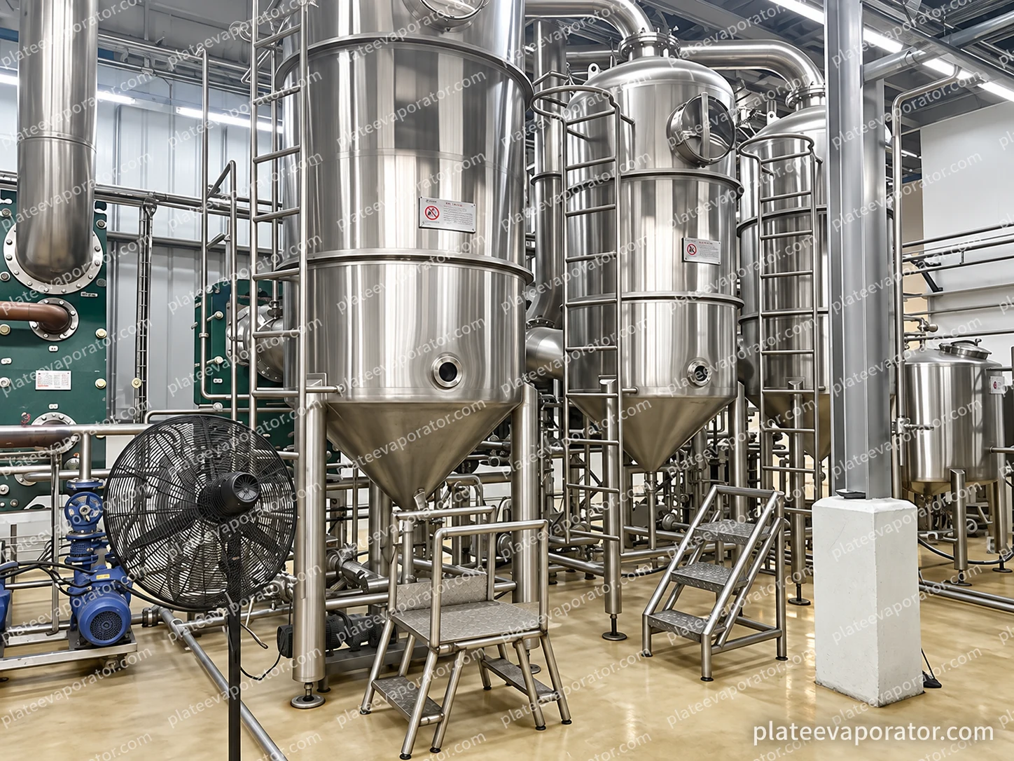
Give vapor and concentrate their own exits
The evaporation section produces a mixture that must separate before vapor continues to the next duty. The vertical vessel provides the separation space and a liquid collection region connected to the product outlet. Its upper pipework carries vapor away from the liquid path.
Liquid level, feed behavior and discharge control influence how the vessel operates. Foaming and entrainment need attention because liquid carried into the vapor route can affect condensate and heat-transfer surfaces farther downstream. The separation arrangement is selected with those product characteristics in view.
Access ports, ladders and surrounding pipework are part of the installed module. Keep the ports reachable and allow space around the lower outlet and valves. Internal separation devices and their maintenance procedure belong to the selected vessel design.
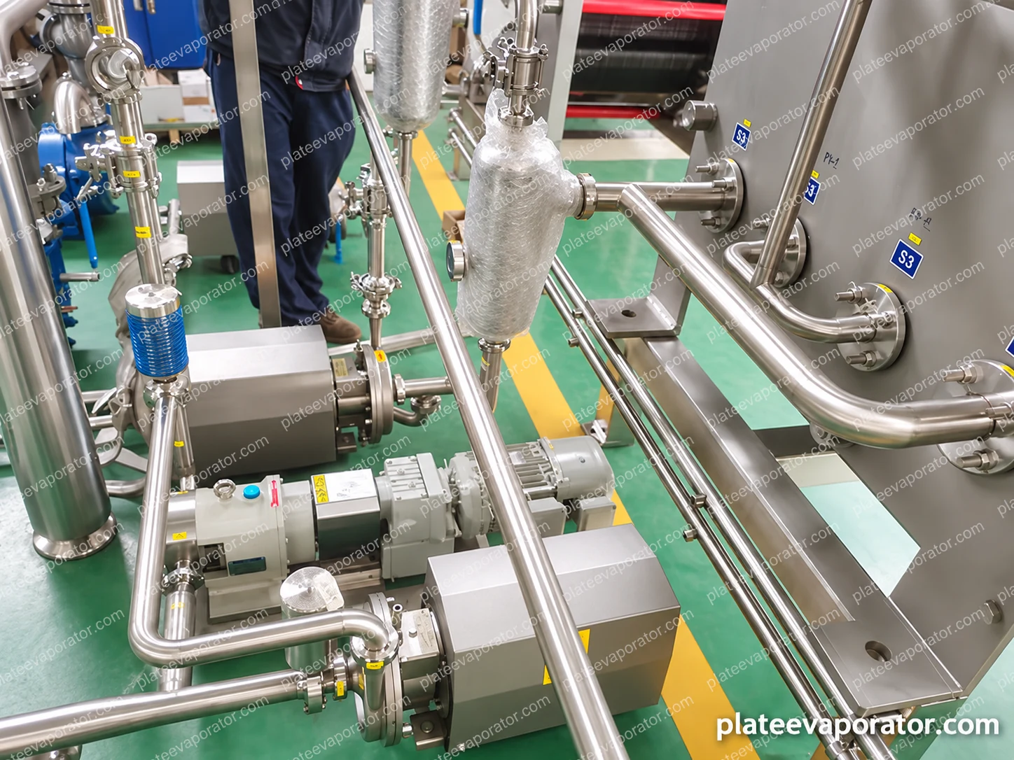
Match each pump to the liquid at that position
Feed, concentrate and condensate are different pumping duties. Concentration changes the product flow and can increase viscosity, while a hot liquid on the vacuum side has different suction conditions from a cool feed supply. The liquid properties, available inlet conditions and receiving pressure govern pump selection.
The connection detail shows compact drives, sanitary pipe joints, valves and several plate-pack ports. The pipe arrangement should provide workable isolation and service access without leaving product trapped in unnecessary branches. Drainage and the cleaning route are considered with the normal transfer duty.
| Liquid duty | Selection basis |
|---|---|
| Feed | Prepared-liquid flow, temperature, suspended material and the receiving circuit |
| Concentrate | Outlet solids, viscosity, operating temperature and onward pressure |
| Condensate | Condensing conditions, available suction and the collection destination |
| Circulation, where included | The selected evaporation arrangement and required liquid movement |
Connect condensation to the required boiling condition
Vacuum operation lowers the boiling temperature relative to operation at atmospheric pressure. The attainable condition still depends on the liquid composition and on the vapor, cooling and gas-removal duties. Product temperature and pressure are therefore considered together across the operating range.
The package includes a condensing and vacuum circuit; a plate condenser is one available arrangement. Cooling supply, condensate removal and non-condensable gas handling must work with the vapor arriving from the evaporation system. Terminal vapor duty changes with the effect and heat-recovery configuration.
Show cooling-water supply and return, condensate collection, vacuum connections and their isolation points on the utility layout. Seasonal cooling-water temperature is relevant to operation, as are startup load and the conditions used to establish vacuum before normal production.
Select the effect arrangement and heating option separately
In a multi-effect arrangement, vapor generated in one stage supplies heat to another operating at a suitable lower pressure. The stages share the available temperature difference; product behavior, heat-transfer area and practical operating range influence the design.
Thermal vapor recompression, or TVR, uses motive steam to raise the pressure of part of the generated vapor for reuse. It is a selected heating configuration, rather than another word for an additional effect. Its duty depends on the available steam and the vapor conditions.
| Configuration | Equipment relationship |
|---|---|
| Single effect | One evaporation effect with its heating and vapor-handling circuits |
| Double or multiple effects | Connected effects that reuse secondary vapor at successive operating conditions |
| TVR option | A steam thermocompressor integrated with the selected vapor and heating circuits |
Reference choices for a configured system
The duty specification distinguishes feed, concentrate and removed water. Feed mass and nonvolatile-solids content provide a basis for the concentration balance; volumetric values also need the density at the stated conditions. A heat-transfer area or a project flow figure should not be used as a universal machine rating.
Operating references do not replace component design limits. The selected plate pack, seals, vessels, pumps and instruments each require compatible pressure, temperature and material specifications.
| Item | Family reference | Application condition |
|---|---|---|
| Operating temperature | 40–90 °C | A family reference dependent on product and vacuum; not a universal process recipe |
| Heat-transfer area | 5–200 m² | A configuration range; area alone does not establish evaporation output |
| Product-contact material | SUS304 or SUS316L | Selected with product chemistry, cleaning exposure and component duty |
| Effect arrangement | Single, double or multiple | Chosen with the water-removal duty and available utilities |
| Controls | PLC with an operator interface | Measurements, sequences and records defined for the configured package |
| Cleaning | CIP connections; supply module as specified | Matched to the equipment circuit and its cleaning procedure |
Coordinate production and cleaning from the control system
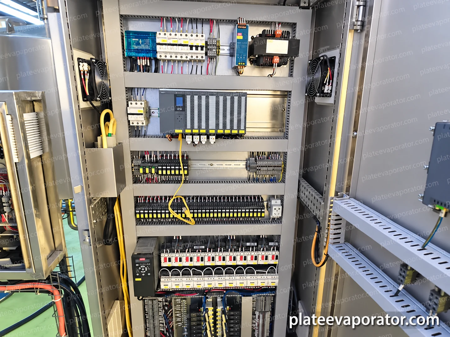
The PLC and operator interface bring together the process measurements and equipment sequence. Temperature, pressure, feed flow and vessel levels support coordinated steam input, liquid transfer and concentrate discharge. Alarms and interlocks address abnormal conditions and the permitted sequence for starting or stopping equipment.
The actual cabinet view shows the controller, input/output modules, protective switching and organized terminal wiring. The selected control specification establishes which values are displayed or recorded, their measurement locations and how the records can be retrieved. Cabinet hardware alone does not define a finished recipe or acceptance result.
CIP connections carry the cleaning solution through the product-contact circuit and return it for the chosen recovery or discharge sequence. A dedicated supply station can be included, or the circuit can connect to a compatible plant system. The valves, plate passages, separator outlets and pump connections all belong in that route.
Cleaning chemistry, flow, temperature and duration follow the product deposits and the limits of the selected seals and materials. Trend changes in pressure drop and thermal performance can help schedule inspection. Opening a plate pack for service is a separate maintenance operation performed after isolation, depressurization and safe cooling.
Set the supply boundary at usable process connections
The evaporator accepts a liquid prepared for its plate passages and separation duty. Filtration or clarification can be arranged ahead of it when the material requires that treatment. For example, the Indonesian coconut-water installation connects upstream phase separation with the evaporation process.
After concentration, the product continues to its chosen cooling, holding, treatment or packing operation. Concentration does not by itself establish a preservation process or storage life. The required outlet condition needs to match the next machine rather than end at an isolated concentrate nozzle.
| Boundary | Connection to establish |
|---|---|
| Incoming liquid | Prepared feed condition, supply pressure and control of interruptions |
| Concentrate outlet | Receiving equipment, temperature and allowable transfer pressure |
| Plant utilities | Heating, cooling, electrical supply, instrument air where needed and drains |
| Cleaning supply and return | Fluid source, circulation route, recovery and discharge |
| Automation | Signals shared with upstream supply and downstream receiving equipment |
Build service access into the installed layout
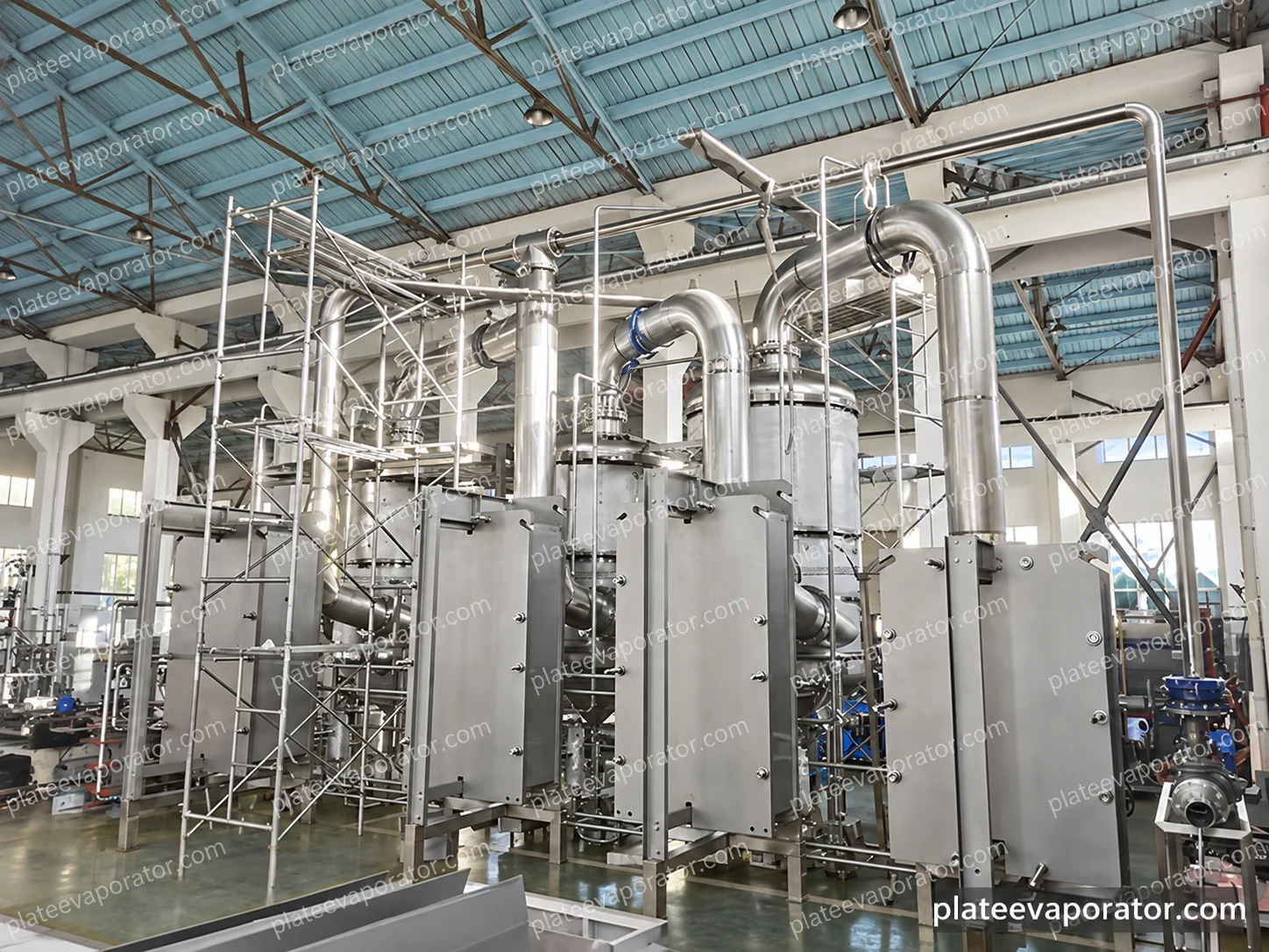
The assembly view brings the plate frames, separators and overhead connections into one structure. Temporary scaffolding makes the height and installation access visible. The completed layout needs permanent access appropriate to valves, instruments and vessel inspection, as well as clear floor space around pumps and plate frames.
Before acceptance, the agreed checks connect the mechanical assembly to its operating duty: circuit identification, drainage, instrument response, control sequences and the specified liquid run. A product trial can then assess concentration, operating stability and cleaning behavior under recorded conditions. The test scope and acceptance limits should accompany the equipment specification.
Further detail
Questions about the equipment
Is the system intended for a liquid with substantial pulp or long fibers?
Plate selection starts from the actual feed and its behavior as concentration rises. Substantial pulp, fibers, high viscosity or rapid fouling can favor another heat-transfer arrangement. Assess the prepared feed and intended outlet together before fixing the evaporation structure.
Can existing plant utilities and cleaning equipment be used?
They can form part of the integration when their supply conditions, return capacity and controls suit the selected package. Define those interfaces alongside the dedicated equipment so that the operating and cleaning circuits remain complete.
Does a three-effect project establish the output for a new product?
No. The new duty follows its feed, required concentration, temperature constraints and utility conditions. Project examples show actual configurations; their reported rates belong to those applications.